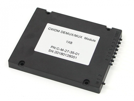
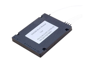
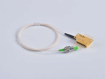
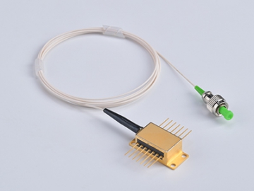
Filter Wavelength Division Multiplexer
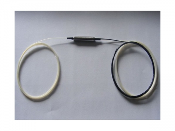
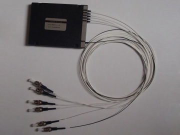
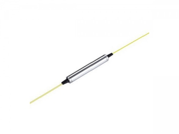
Pictures and Schematic Diagram
The thin-film filter based wavelength division multiplexer is utilized to combine and separate optical signals in an FTTP network. The use of WDM technology expands the capacity of single fiber, as it allows multiple light signals to be conveyed at the same, in parallel and over single fiber. Thanks to WDM technology, two-way communications become more manageable and efficient. The filter wavelength division multiplexer is widely used in optical network upgrade and expansion.
Features of Filter Wavelength Division Multiplexer
Wide Operating Wavelength Range
Ultra Flat Wide Passband
High Channel Isolation
Low Insertion Loss
High Stability and Reliability
Epoxy Free Optical Path
Applications of Filter Wavelength Division Multiplexer
System Monitoring
WDM System
Transmitters and Fiber Lasers
Fiber Optical Amplifier
Fiber-optic Instruments
Technical Specifications of Filter Wavelength Division Multiplexer
| Optical Multiplexer Parameters | 1310/1550nm MWDM | 1310/1490/1550nm MWDM | 980/1550nm MWDM | |
| Pass Channel Wavelength Range (nm) | 1260~1360(1520~1600) | 1480~1500 | 1525~1565 | |
| Reflect Channel Wavelength Range(nm) | 1520~1600(1260~1360) | 1260 ~ 1360 & 1530~1570 | 970~990 | |
| Insertion Loss (dB) | Pass Channel | < 0.6 | < 0.6 | < 0.8 |
| Reflect Channel | < 0.5 | < 0.5 | < 0.7 | |
| Insertion Loss Variation(dB) | Pass Channel | < 0.3 | < 0.3 | < 0.3 |
| Reflect Channel | < 0.2 | < 0.3 | < 0.3 | |
| Isolation (dB) | Pass Channel | >40 | >30 | >30 |
| Reflect Channel | >15 | |||
| Insertion Loss Temperature Sensitivity (dB/°C ) | < 0.005 | |||
| Polarization Dependent Loss (dB) | < 0.1 | |||
| Polarization Mode Dispersion (ps) | < 0.1 | |||
| Directivity (dB) | >50 | |||
| Return Loss (dB) | > 50 | |||
| Max Power Handling (mW) | 300 | |||
| Operating Temperature (°C) | 0 ~ 70 | |||
| Storage Temperature (°C) | -40 ~ 85 | |||
| Dimension(mm) | 5.5×35 | |||
Note: All insertion loss doesn’t include connector loss. For multiplexing units with connectors, the insertion loss will be 0.3 dB higher
Order Information
MWDM-A-B-C-D-E-F-G
