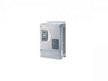
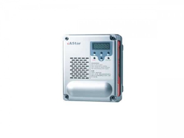
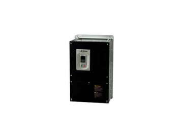
Elevator Inverter
AS320 elevator inverter is a kind of newly developed frequency inverter especially for elevators. It is designed with 32-bit MPU for motor driving, high performance complex programmable logic device (CPLD), and advanced power module. Meanwhile, the elevator inverter is designed based on international advanced closed loop vector control technology and supports various control modes including V/F control, sensorless vector control, and torque control modes. Integrating the characteristics of potential energy load, the elevator inverter allows elevators to operate efficiently, smoothly and steadily, and offers passengers a comfortable feeling.
The elevator inverter is designed based on innovative load-sensorless start compensation technology, which helps ensure comfortable feeling at the starting moment without installation of a weight measuring device. Meanwhile, incremental ABZ encoder is utilized to achieve control of the synchronous motor. In addition, new type PWM inverter dead time compensation method and dynamic PWM carrier modulation technology help effectively reduce the noise and losses in electric motors. By making improvement on inverter hardware, our elevator inverters offer a maximum junction temperature of 175℃ and low switch loss.
Main Features
1. Closed loop vector control technology ensures high performance.
2. Zero-speed torque compensation without load weighing device helps to save cost.
3. New PWM dead-zone compensation technology of the elevator inverter results in less energy loss.
4. Dynamic PWM carrier modulation technology for less motor noise.
| Model | Rated capacity (kVA) | Rated output current (kA) | Applicable motor power (kW) |
| 2S01P1 | 2.3 | 6.0 | 1.1 |
| 2S02P2 | 4.6 | 12 | 2.2 |
| 2S03P7 | 6.9 | 18 | 3.7 |
| 4T02P2 | 4.7 | 6.2 | 2.2 |
| 4T03P7 | 6.9 | 9 | 3.7 |
| 4T05P5 | 8.5 | 13 | 5.5 |
| 4T07P5 | 14 | 18 | 7.5 |
| 4T0011 | 18 | 27 | 11 |
| 4T0015 | 24 | 34 | 15 |
| 4T18P5 | 29 | 41 | 18.5 |
| 4T0022 | 34 | 48 | 22 |
| 4T0030 | 50 | 65 | 30 |
| 4T0037 | 61 | 80 | 37 |
| 4T0045 | 74 | 97 | 45 |
| 4T0055 | 98 | 128 | 55 |
| 4T0075 | 130 | 165 | 75 |
Technical Specifications of the Elevator Inverter
| Item | Technical index | |
| Max. output voltage (V) | Three phase, 380/400/415/440/460V | |
| Input power supply | Phase number, voltage, frequency | Three-phase, 380/400/415/440/460V 50/60Hz |
| Allowable voltage change | -15% ~ 10% | |
| Allowable frequency change | -5% ~ 5% | |
| Elevator inverter operation condition when voltage dips | When voltage is AC300V or above: operate continuously When the rated input voltage drops to a voltage below AC300V: under-voltage protection is available in 15ms. | |
| Control characteristic | Control mode | Vector control with PG card V/F control Open loop vector control Torque control |
| Starting torque | 150%: 0Hz (PG card vector control) 120%: 0.5Hz (V/F control) 150%: 0.5Hz (open loop vector control) | |
| Speed control range | 1:1000 (vector control with PG card) 1: 200 ( vector control without PG card) | |
| Speed control precision | ±0.02% (vector control with PG card, 25 ±10 ℃); ±0.2% (vector control without PG card 25 ±10 ℃) | |
| Torque limitation | Available through parameter setting | |
| Torque precision | ±5% | |
| Frequency control range | 0 ~ 120Hz | |
| Frequency precision (temperature fluctuation ) | ±0.01% (Digital command, -10 ~ 45℃ ) ±0.1% (Analog command, 25 ±10 ℃) | |
| Preset frequency resolution | 0.01Hz (Digital command) ±0.06Hz/120Hz (Analog command, 11bit unsigned) | |
| Output frequency resolution | 0.01Hz | |
| Overload capacity | Zero speed: 150% , < 3Hz: 160%, > 3Hz: 200% | |
| Braking torque | 150% (external brake resistor), built-in brake unit | |
| Acceleration / deceleration time | 0.01 ~ 600s | |
| Carrier frequency | 2 ~ 11kHz | |
| Speed setting | Digital setting, analog setting, control panel setting | |
| Storage battery operation | If power failure occurs, the elevator inverter allows the elevator to work on storage batteries at a low speed, thus enabling the elevator to stop at the nearest floor | |
| PG card interface signal | PG-card power supply | 5V, 12V, 300mA |
| PG-card signal type | Open collector, push-pull, differential, SIN/COS, Endat absolute types | |
| PG-card frequency divided output | OA and OB orthogonal, dividing frequency coefficient: 1-128 | |
| Control signal input/output | Analog voltage input | 2 input channels, -10 ~ 10VDC, precision 0.1% |
| Analog voltage output | 2 output channels, -10 ~ 10VDC, precision 0.1% | |
| Opto-isolator input | 8 input channels, input function is user-defined | |
| Open collector output | 4 output channels, output function is user-defined | |
| Programmable relay output | 2 output channels, normally open and closed contacts are available; Contact capacity: resistance: 5A 250VAC or 5A 30VDC Output function is user-defined | |
| RS485 communication signal | 1-channel, | |
| RS232 communication interface | 1-channel, used for connection to control system or PC | |
| Protection functions | Motor overload protection | The function is available through parameter setting |
| Elevator inverter overload protection | < 3Hz: 160%, 5 seconds > 3Hz : 185%, 10 seconds | |
| Short circuit protection | Protect the elevator against over-current caused by short circuit of any two output phases | |
| In-operation input phase loss protection | During operation, if there is input phase loss, output is stopped to protect the elevator inverter | |
| In-operation output phase loss protection | During operation, if there is output phase loss, output will be stopped to protect the elevator inverter | |
| Over-voltage threshold | Bus voltage 410V(200V series), 810V(400V series) | |
| Under-voltage threshold | Bus voltage 180V (200V series), 380V(400V series) | |
| Instantaneous power off compensation | Protection over 15ms | |
| Overheat of radiation fins | Protection is available through thermistor | |
| Speed loss protection | Available when the operation speed variation is over 30% of rated speed | |
| Impulse encoder failure protection | Disconnect PG | |
| Braking unit protection | Automatic diagnosis of braking unit failures, and then give protections | |
| Module protection | Include overcurrent, short circuit and overheat protections | |
| Current sensor protection | Auto detect when powered on | |
| Reversed-speed protection | Detect through encoder | |
| I ²t protection | Detect through 3-phase current | |
| Over-high input voltage protection | 400V series: > 725V 200V series: >360V Detect when stopped | |
| Output ground fault protection | If there is any short circuit to ground during operation, the output will be stopped to protect the elevator inverter | |
| Output unbalance protection | If there is unbalanced output current, the output will be stopped to protect the elevator inverter | |
| Short circuit protection for brake resistor | Detect while braking | |
| Encoder interference | Evaluate the encoder interface degree and alarm | |
| EEPROM failure | Detect when powered on | |
| Display | LCD display | All sub-menus |
| Operation environment | Ambient temperature | -10 - 45℃ |
| Humidity | 95%RH or below (no condensing) | |
| Storage temperature | -20 ~ 60℃ (storage during short term transportation) | |
| Application places | Indoor (without corrosive gas and heavy dust) | |
| Altitude | 1000m or lower | |
| Structure | Protection class | IP20 |
| Cooling method | Forced air cooling | |
| Installation method | In cabinet | |
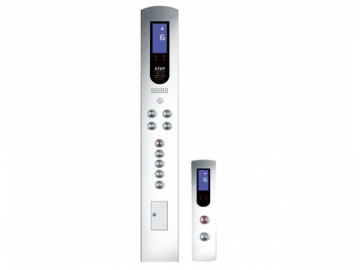
We are a major elevator inverter manufacturer and supplier in China. We offer various types of products such as general vector inverter, elevator group control system, energy regenerator and car controller board.
