Cement Mill
Cement pre-grinding is a production process used to grind raw material to a specified size so that it can be more easily processed by a final grinder, turning the material into fine particles.
Sinomaly specializes in cement milling solutions, offering a range of mills from 2.6m to 4.8m in diameter and with power up to 4200kW. Our dedication to continuous improvement is driven by the specific needs of our customers, ensuring that every mill we provide is reliable, safe, and highly efficient. This commitment to delivering tailored, high-performance equipment underlines our role in advancing cement production technology.
| Model | Grinding Roller Quantity | Main Motor Power (kW) | Matched Ball Mill Model(m) | Matched Ball Mill Power(KW) | System Capacity(t/h) |
| 3 | 1120~1250 | Φ3.2×13 | 1600 | 115~125 | |
| 3 | 1250~1400 | Φ3.2×13 | 1600 | 120~130 | |
| 3 | 1400~1600 | Φ3.2×13 | 1600 | 125~140 | |
| 3 | Φ3.8×13 | 2500 | 140~155 | ||
| 3 | Φ4.2×13 | 3550 | 160~180 | ||
| 3 | 1800~2000 | Φ3.8×13 | 2500 | 160~180 | |
| Φ4.2×13 | 3550 | 175~195 | |||
| 3 | 2240~2500 | Φ3.8×13 | 2500 | 175~195 | |
| Φ4.2×13 | 3550 | 195~215 | |||
| 3 | 2500~2800 | Φ3.8×13 | 2500 | 190~210 | |
| Φ4.2×13 | 3550 | 210~230 | |||
| 3 | 2800~3150 | Φ4.2×13 | 3550 | 225~250 | |
| Φ4.6×14 | 4200 | 250~270 |
| Model | Grinding Roller Quantity | Main Motor Power(KW) | Capacity(t/h) |
| LRMK32.2, 3, 4 | 2, 3, 4 | 1600~1800 | 65~80 |
| LRMK36.2, 3, 4 | 2, 3, 4 | 2000~2240 | 75~90 |
| LRMK38.2, 3, 4 | 2, 3, 4 | 2240~2500 | 90~105 |
| LRMK43.2, 3, 4 | 2, 3, 4 | 3000~3150 | 125~145 |
| LRMK46.2, 3, 4 | 2, 3, 4 | 3350~3550 | 140~160 |
| LRMK50. 2, 4 | 2, 4 | 4000~4200 | 155~180 |
| LRMK53.2, 4 | 2, 4 | 4300~4500 | 175~205 |
| LRMK56.2, 4 | 2, 4 | 4800~5000 | 190~225 |
| LRMK60.2, 4 | 2, 4 | 5200~5400 | 200~235 |
Remarks: Material Moisture ≤5%; Material granularity ≤30mm; Material Ratio: Clinker 85%, Gypsum 5%, Admixture 10%; Product Specific Surfaces Area ≥360 m2/kg; Product Moisture≤ 0.5%
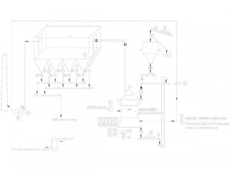
The cement clinker is sent from the feeding pipe to the center of the grinding table through the feeder, and the electric motor drives a reduction gear to rotate the grinding tabel, and the material is evenly dispersed and layered under the centrifugal force to form a material bed with a certain thickness. Depending on the rocker arm, the grinding roller exerts force on the material bed through the loading cylinder. After rolling, the material overflows to the edge of the grinding table. Meanwhile, it enters to the separator due to the hot air flow from the air ring. The fine material is brought out from the separator to the dust collector, and the coarse material falls into the outflow system for second grinding.
Grinding roller
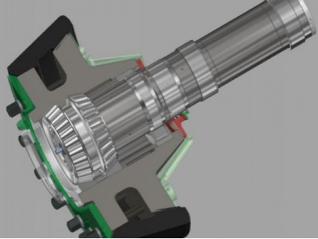
The grinding roller is a device that puts pressure on the material and crushes it on the grinding table. Under constant pressure, the shape and size of the grinding roller have a direct impact on the grinding efficiency of the material.
- Grinding roller structure
- Sketch map of grinding roller after assembling
- Pre grinding roller
- Finish grinding roller
Lubrication and airtight seal for the grinding roller bearing
Using oil for forced lubrication, and monitoring the temperature at any time ensures the normal operation of grinding roller, improving service life.
Rocker arm
A rocker arm is a component that connects the grinding roller and tension device. The pulling force produced by hydraulic cylinder is transferred from the rocker arm to the grinding roller.
Grinding table
There is a lining plate installed on the grinding table. The surface of the lining plate is made of wear-resistant material using a weld overlay, and can be re-welded after it is worn down and is suitable for reuse. The outer edge of the grinding table is equipped with a dam ring, and the height can be adjusted to control the thickness of the material layer. The periphery of the grinding table is an air ring. The hot air enters the lower housing from the air inlet, and then rises uniformly through the air ring, carrying the fine material into the upper separator. Some large particles fall into the lower housing through the air ring, and are scraped out of the grinding mill by the scraper installed on the grinding table, and re-enter the cement mill through external circulation.
Housing
The cement mill housing has three parts: the lower housing, the middle housing and the housing of the separator, and they are welded into place.
Tension device
The tension device includes a hydraulic station, hydraulic cylinder, accumulator and its pipeline. The hydraulic cylinder is pressurized in both directions. When the cement mill starts or stops feeding during operation, the grinding roller can be raised by reverse pressurization to achieve no-load start and no-load maintenance.
Separator
SINOMALY adopts the most advanced vortex plane sorting principle to design the separator for high working efficiency. The transmission adopts AC motor with variable frequency speed regulation, so the operator can adjust conveniently according to different requirements such as product fineness and production status.
Cement mill foundation
The front frame is the basic frame of the entire cement mill, and the columns and reducers are located on the frame to become a whole. The front frame is welded from profiled steel and has an adjustment mechanism to adjust the level of the frame conveniently.
- Foundation base installation
- Trial assembly of mainframe in the factory
- Cement mill stand installing
- Mill stand
Cement mill drive
The drive consists of a vertical mill reducer, a diaphragm coupling, a main motor and a gear reducer, etc.
Rotary feeder
The feeding device of the vertical raw mill adopts rotary feeder, which has the advantages of simple airtight structure, stable operation and continuous feeding. The wear-resistant liner of the housing is machined metal, featuring high precision; the gap between the blade and the wear-resistant scraper is adjustable, both of which are wearing parts and can be replaced. Hot air enters through both sides of the housing to prevent the feeder from clogging.
Turning device
Each grinding roller is supported separately, and the door on the housing can be opened during the overhaul. The grinding rollers can be easily turned out of the grinding mill by means of the vertical mill hydraulic cylinder, and for overhaul and maintenance, the roller sleeve can be easily disassembled and removed.
Mechanical limit electrical limit protection device and material layer detection device
Hydraulic system
The main valves and oil pumps are purchased from trusted brands; The hydraulic system is equipped with a double cylinder filter. The normal operation vibration of the grinding mill can be controlled within <1.5-2.0 mm/s. The fluctuation of system can be effectively reduced to avoid damage or efficiency loss caused by grinding roller fault or strong vibration.
Accumulator
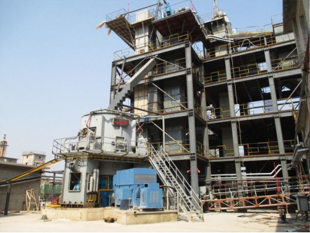
- LRMK43.4 Vertical mill for final milling of clinker
- LRMP32.3 Cement pre-grinding vertical mill


