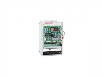
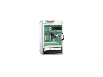
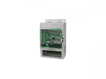
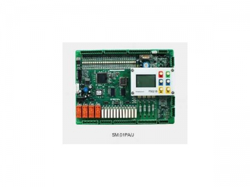
Elevator Integrated Drive and Controller
While designing the AS380 elevator integrated drive and controller, a variety of factors, including elevators' safety and reliability, inherent characteristics of elevator operation, and potential energy load characteristic of elevators, are taken into consideration. Designed based on variable frequency speed regulation technology and elevator control technology, the elevator integrated drive and controller is an ideal combination of an elevator drive and an elevator controller. Its dual 32-bit embedded microprocessor unit allows it to complete both elevator operation and motor drive functions. The multiple elevator operation functions can satisfy customers' different application requirements. In addition, the elevator integrated drive and controller offers improved performance, usage convenience, and economical efficiency, and it also features compact structure, small size, few wire connection and high reliability.
Why Choose the Elevator Integrated Drive and Controller?
1. Elevators with the integrated drive and controller offer higher safety standard, because the control system and drive system both offer safety protection functions. Meanwhile, the anti-interference capability of the integrated system is exceeding the highest level of related industrial standard.
2. Due to CAN bus serial communication, the elevator integrated drive and controller is provided with simple wire connection, strong data transmission capability and high reliability. It also offers high compatibility, as it is applicable for both synchronous motors and asynchronous motors. Incremental ABZ encoders can be utilized to achieve synchronous motor control.
3. The adoption of advanced vector control technology allows the elevator integrated drive and controller to offer superior motor speed regulation performance, thus enabling the elevator to offer passengers comfortable feeling. Our newly developed load sensor free start compensation technology also allows the elevator to provide comfortable feeling while starting without installation of a weighting device.
4. The elevator integrated drive and controller offers elevators higher operation efficiency, and it also offers group control function. It is able to control maximally eight elevators synchronously, and also supports group control of elevators aiming to the same floors.
5. Designed based on new PWM dead time compensation technology and dynamic PWM carrier modulation technology, the elevator integrated drive and controller is able to reduce motor noise and motor loss effectively.
6. Due to improved hardware design, the elevator integrated drive and controller offers a maximum junction temperature of 175℃, low switch loss. This ensures the long service life of the equipment.
Main Features
1. The elevator integrated drive and controller is designed with closed loop vector controller for higher performance.
2. Zero-speed torque compensation system without load weighing device helps save cost.
3. New PWM dead-zone compensation technology is conducive to energy conservation.
4. Dynamic PWM carrier modulation technology ensures reduced motor noise.
5. The elevator integrated drive and controller is suitable for both synchronous and asynchronous motor.
6. Dual 32-bit embedded microprocessor.
7. Incremental encoder is employed to control synchronous motor.
8. This product is applicable for residential lift, goods lift, car lift, ramp elevator, etc.
Elevator Integrated Drive and Controller Model List
| Model AS380- | Rated capacity(kVA) | Rated output current(kA) | Applicable motor(kW) |
| 2S01P1 | 2.3 | 6.0 | 1.1 |
| 2S02P2 | 4.6 | 12 | 2.2 |
| 2S03P7 | 6.9 | 18 | 3.7 |
| 4T02P2 | 4.7 | 6.2 | 2.2 |
| 4T03P7 | 6.9 | 9 | 3.7 |
| 4T05P5 | 8.5 | 13 | 5.5 |
| 4T07P5 | 14 | 18 | 7.5 |
| 4T0011 | 18 | 27 | 11 |
| 4T0015 | 24 | 34 | 15 |
| 4T18P5 | 29 | 41 | 18.5 |
| 4T0022 | 34 | 48 | 22 |
| 4T0030 | 50 | 65 | 30 |
| 4T0037 | 61 | 80 | 37 |
| 4T0045 | 74 | 97 | 45 |
| 4T0055 | 98 | 128 | 55 |
| 4T0075 | 130 | 165 | 75 |
Technical Specification of Elevator Integrated Drive and Controller
| Maximum voltage output (v) | 200V-class: 1-Phase, 220~240 (matching with voltage input) 400V-class; 3-Phase, 380/400/415/440/460V (matching with voltage input) | |
| Input power | Phase, voltage, frequency | 200V-class,1-Phase220~240V, 50~60Hz |
| Allowed fluctuation in voltage | -15%~ 10% | |
| Allowed fluctuation in frequency | -5%~ 5% | |
| Instantaneous voltage drop | 200V-class: Keep running when the voltage is above AC150V; Under-voltage protection is available in 15ms when the voltage is below AC 150V. 400V-class: Keep running when the voltage is above AC300V; Under-voltage protection is available in 15ms when the voltage is below AC 300V | |
| Basic Characteristics | Max. floors | 2 to 64 floors for single elevator |
| Speed limitation | ≤ 4.00m /s | |
| Number of Elevators in group control | ≤8 | |
| Communication type | CAN-BUS Serial Communication | |
| Drive Characteristics | Control type | Vector control with PG-card |
| Startup Torque | 150% 0Hz (Vector control with PG-card ) | |
| Speed control range | 1:1000 (Vector control with PG-card ) | |
| Speed Control Precision | ±0.02% (Vector control with PG card 25 ±10 ℃) | |
| Torque Limitation | Exists (adjustable by parameter) | |
| Torque Precision | ±5% | |
| Frequency Control Range | 0 ~ 120Hz | |
| Frequency Precision (Temp. fluctuation) | ± 0.1% | |
| Preset frequency resolution | ±0.06Hz /120Hz | |
| Frequency Output Resolution (Calculated Resolution) | 0.01Hz | |
| Startup compensation without load | Under circumstances of unknown elevator load, suitable torque will be given to the motor according to the movement direction of the elevator, allowing the elevator to start smoothly and instantaneous. Rope slipping possibility can be reduced to minimum for more comfort at the start. | |
| Overload Capacity | Zero Speed(150% overload) , < 3Hz(160% overload), > 3Hz (200% overload) | |
| Braking Torque | 150% (connecting external braking resistor), built-in braking unit | |
| Accelerating/Decelerating time | 0.01 ~ 600s | |
| Carrier Frequency | 2 ~ 11kHz | |
| Storage Battery Operation | If power failure occurs, storage batteries are used to bring the elevator slowly to the nearest landing | |
| PG Card Connection | PG Card Power Supply | 5V, 12V, 300mA |
| PG Card type | Open collector, Push-Pull, Differential, SIN/COS, Endat Absolute types | |
| PG-Card Frequency Divided Output | OA and OB orthogonal, dividing frequency coefficient 1 ~ 128 | |
| Control Input /Output Signal | Power supply for opto-isolated input control | Isolated 24V DC |
| Power supply control for Relay-output | Isolated 24V DC | |
| Opto-isolated low-voltage input | 20-channel, switching value input, OPTO-isolated control signal is isolated 24V DC power supply input signal | |
| Opto-isolated high-voltage input | 4-channel, switching value input, OPTO-isolated control signal is isolated 24VDC power supply input signal | |
| Programmable Relay Output 1 | 4-channel, normal open contact, SPST Contact resistance: 3A 250VAC or 3A 30VDC; | |
| Programmable Relay Output2 | 3-channel, normal open contact, SPST Contact resistance: 6A 250VAC | |
| CAN communication signal | 3- channel | |
| Analog input | 1- channel, single-ended or differential; input voltage range: -10v~ 10v, precision: 0.1% | |
| Protection Functions | Motor Overload Protection | Available through parameter setting |
| Inverter Overload | < 3Hz (160% overload): 5seconds, > 3Hz(185% overload): 10seconds | |
| Short-circuit Protection | Protection for drive, activated when there is overcurrent caused by short circuit of any two phases at the output side | |
| Input Phase-loss Protection During Running | When there is input phase loss during running, the circuit will be switched off to protect the drive | |
| Output Phase-loss Protection During Running | When there is output phase loss during running, the circuit will be switched off to protect the drive | |
| Over-Voltage Threshold | 410V on bus (200V series), 810V(400V series) | |
| Under-Voltage Threshold | 180V on bus (200V series), 380V(400V series) | |
| Instantaneous Power-off Compensation | Protection over 15ms | |
| Over-heating of Radiation Fins | Protection through thermistor | |
| Speed Loss Protection | Protection is available when the speed is over 30% of the rated speed | |
| Impulse Encoder Fault | Disconnection for PG | |
| Braking Unit Protection | Automatic diagnosis of braking unit failure, and then give protection | |
| Module Protection | Include Over-current, Short-circuit and Over-heat protection | |
| Current Sensor Protection | Automatic detection when powered on | |
| Speed Reverse Protection | Detection through Encoder | |
| I ²t Protection | Detection through 3-phase current | |
| Input Over-Voltage Protection | 400V-class>725V, 200V-class>360V, Detect when stopped | |
| Output Ground Fault Protection | If there is any short circuit to ground during operation, the circuit will be switched off to protect the Drive | |
| Output Unbalanced Protection | If there is unbalanced output current, the circuit will be switched off to protect the Drive | |
| Short-Circuit of Brake Resistor Protection | Detect while braking | |
| Encoder Interference | Evaluate the encoder interface degree and alarm | |
| EEPROM Faults | Self-test when powered on | |
| Display | Chinese and English LCD display | All sub-menus |
| Environment | Ambient temp. | -10 ~ 45℃ |
| Humidity | Below 95%RH (no condensation) | |
| Storage temp. | -20 ~ 60℃ (for short-term transport) | |
| Application Places | Indoor (without corrosive gas and dust) | |
| Altitude | Below 1000m | |
| Structure | Protection Class | IP20 |
| Cooling Method | Air-blast cooling | |
| Installation Type | In cabinet | |
As a China-based elevator integrated drive and controller manufacturer, we also offer harbor crane 4-quadrant inverter, servo drive, parallel VVVF control cabinet, elevator group control system, and much more.
