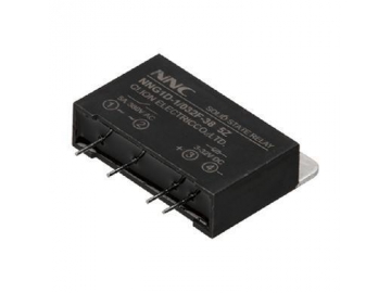
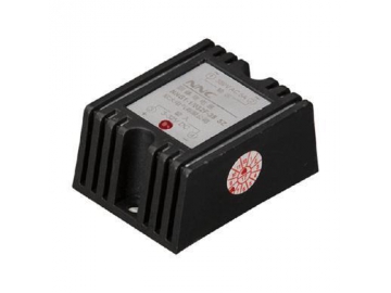
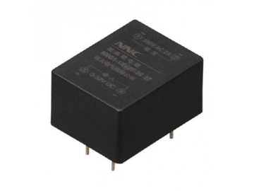
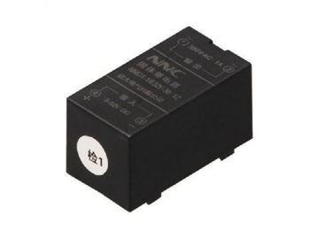
DC-AC Single Phase Solid State Relay
The NNG series of DC-AC single phase solid state relay adapts the international popular circuit and manufacture technique, which accord with the requirements of GB14048.5. The relay features strong compact structure, impact resistance, good shock resistance, no spark, no noise, high working reliability and long use age. The relay is used in the automatic control filed like signal light, scintillator, stage lighting control system, instrument and apparatus, medical equipment, copier, automatic washing machine, automatic fire equipment and security system, and it also can be used as the selector switch of the power capacitor which be compensated by the network power factor. In addition, the relay is widely used in the bad environment and frequent switching occasions like the chemical industry and coal industry which need prevent from explosion, damp, dust and erosion.
- Both of the internal output terminals of the solid state relay have an RC circuit, and it has the small load with a leakage current of, ≤10mA. It is normal to have the phenomenon of voltage output or break-over voltage.
- The controlled silicone of the output terminal has the voltage decreasing ≤1.5v in the break-over state, which leads to solid state relay heating. So the user should install the heat sink when using the relay, and the user must spare enough space when installing the relay in the equipment cabinet.
- The model selection guide of the heat sink refers to attachment 1.
- The marked output voltage and current of the solid state relay is the rated voltage and rated current, the user should de-rate the value when selecting the model. Different loads have different derating values, and its specific value is referred to in attachment 2. To the inductive load multiple, the user should install the multiple piezo resistor on the output terminal to protect the device.
| Load current | Heat sink model |
| Below single phase 20A | NN-060 |
| Below single phase 40A | NN-061 |
| Below single phase 60A | NN-062 |
| Below single phase 80A | NN-063 |
| Below three-phase 20A | NN-035 |
| Load current | Heat sink model |
| Below three- phase 30A | NN-034 |
| Below three- phase 40A | NN-036 |
| Below three- phase 80A | NN-037 |
| Below three- phase 150A | NN-038 |
| Below three- phase 250A | NN-039 |
| Load mode | Pure resistance | Heating wire | Incandescent lamp | Transformer |
| Power factor | 1.0 | 0.7 | 0.5 | 0.4 |
| Magnification times | 1.5 times | 2 times | 2.5 times | 4 times |
| Load type | Electromagnet | Single phase motor | Three-phase motor | Capacitor switching |
| Power factor | 0.5 | 0.2 | 0.3 | Surge current |
| Magnification times | 4 times | 7 times | 6 times | 10 times |
Example 1: The user will choose the solid state relay with suitable ampere in the situation where the load mode is a heating wire load (power factor is 0.7) and practical working current is 10A?
According to the estimation method of attachment 2, we can conclude as follows:
10A(practical working current)× 2(magnification times)=20A
Therefore, the user should choose the solid state relay with 20A in this example.
Example 2: The user will choose the solid state relay with suitable ampere in the situation that load mode is single phase motor load(power factor is 0.2) and practical working current is 10A?
According to the estimation method of attachment 2, we can conclude as follows:
10A(practical working current)× 7(magnification times)=70A
Therefore, the user should choose the solid state relay with 70A in this example.
- Please pay attention to the arrangement of the relay working voltage and positive pole and negative poles.
- The user should increase the input current when the environmental temperature is low, and the user should decrease the input current when the temperature is high, to guarantee the normal operation of the solid state relay.
- The integrated circuit should have enough load capacity and low “0” level output when it directly drives the SSR.
- In order to guarantee the reliability of the SSR, the user should use the limit parameters of the SSR and utilize the necessary protection methods.
- Selection of peak voltage: inductive load: the 2-3 time of line voltage (effective value), pure resistance load: the 1-2 time of line voltage (effective value).
- Selection of piezoresistor: the nominal working voltage value of the piezoresistor is 1.8-2 times the working voltage effective value of the SSR.
- Please install the relay with the operational current below 5A nearby the heat dissipation window with good ventilation.
- The relay with operational current above 10A must be installed with the heat sink and filling thermal silicone grease between relay and heat sink can dissipate the heat well. And when the surface temperature of the heat sink is close to 60℃, the relay should be force cooled by wind.
- In order to avoid a high temperature rise of the solid state relay, the user should take heat dissipation effect and installation site into consideration when applying the relay. The user needs to spare suitable space when installing two or multiple relays.
Clion offers its global customers a wide range of electronic switching devices with their high quality electromagnetic relays, solid state relays, solid state voltage regulators, and miniature snap action switches among a whole catalog of additional products. We have fully equipped automatic production and assembly lines as we offer superior quality electrically operated switches with thousands of models to choose from.
Index
relay switch, electric switch, switching device
