Hydraulic Briquetting Machine
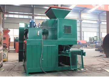
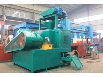
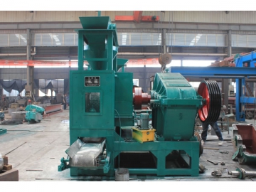
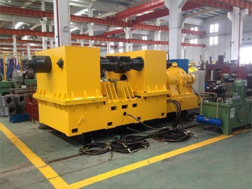
YUKE hydraulic briquetting machine is equipped with hydraulic system which makes it different from common briquette machine. Thanks to the hydraulic device, the pressure for compressing raw materials can keep constant. In addition, when bigger or harder materials enter into rollers, the hydraulic system will work to protect the roller and ensure higher briquetting efficiency.
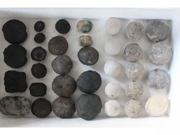
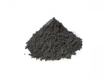
The hydraulic briquette machinery is widely used in various industries, including metallurgy, chemical, refractory material, energy, transportation and heat supply industry, etc. for compressing all kinds of mineral powders and chemical powders. To be specific, this hydraulic briquette making machine has been highly recognized by some enterprises such as briquette plant, steel plant, power plant, chemical plant, cement plant, etc. The hydraulic briquetting machine can form materials into wide variety of shapes, and specifically shaped briquette can be customized if required.
Working Principle
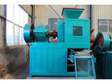
YUKE briquetting machine consists of three parts, namely feeding part, drive part and briquette molding part (main body).
1. Feeding Part
The feeding part is mainly used to achieve ration feeding so as to ensure that the materials can be fed into the rollers uniformly. Specifically, the screw feeder, driven by electromagnetic speed-adjustable motor, presses materials into the main feeding port compulsively by means of the belt pulley and worm reducer. Owing to constant torque, the motor can keep constant feeding pressure, ensuring stable briquette quality.
2. Drive Part
The main drive system of the briquetting machine is composed of motor, triangle belt, reducer, exposed gear and rollers. The power generated by the electromagnetic speed-adjustable motor transmits to the driving shaft through belt pulley, reducer and coupler, and the driving shaft will turn synchronously with the driven shaft by the exposed gear.
3. Briquette Molding Part
The core of the briquette molding part is the rollers. Through rollers, the raw materials can be compressed into briquettes with various shapes. In addition, the rollers feature overload protection, hence keeping sound quality.
| Model | ||||
| Diameter(mm) | 530 | 650 | 750 | 850 |
| Width(mm) | 196 | 196250 | 196250 | 196250 |
| Max lineal pressure ratio(t/cm) | 5 | 6 | 6 | 8 |
| Total pressure(t) | 100 | 110 | 120 | 300 |
| Power(kw) | 45 | 5575 | 7590 | 7590 |
| Precompressed power(kw) | 11 | 15 | 18.5 | 18.5 |
| Power of the oil pump(kw) | 1.5 | 1.5 | 2.2 | 3 |
| Speed(r/min) | 9 | 9 | 9 | 9 |
| Capacity(t/h) | 2-4 | 5-8 | 8-12 | 9-15 |
| Size of the ball(mm) | 38*25*13 (Defined by users) | |||
Note: Above technical parameters are for reference and can be separately designed according to customer's actual situation. In addition, above briquetting machines can be separately equipped with hydraulic system.
| Model | Roll diameter(mm) | Capacity(t/h) | Power of oil pump(kw) | Power(kw) | Briquettes shape and size |
| 290 | 1-3 | 1.1 | 5.5 | Defined by users | |
| 360 | 4-6 | 1.1 | 11-15 | ||
| 430 | 6-8 | 1.1 | 15-18.5 | ||
| 500 | 8-12 | 1.5 | 18.5-55 | ||
| 650 | 10-15 | 1.5 | 37-45 | ||
| 750 | 15-20 | 1.5 | 75-110 | ||
| 850 | 20-25 | 2.2 | 90-110 | ||
| 1000 | 25-35 | 2.2 | 90-132 |
Process Flow
Briquetting Line Process Flow Chart
1. Materials
2. Conveyer
3. Mixer/silo
4. Rotary dryer
5. Dosing machine
6. Mixer
7. Binder mixer
8. Add density machine/Wheel mill
9. Rated silo
10. Briquette machine
11. Chain plate/Mesh belt dryer
12. Vertical dryer
Notes: This flow chart can be also designed based on customers'actual demand.
1. Raw Material
2. Rated Silo
3. Conveyor
4. Frame
5. Inlet
6. Screw Forcing Feeding Device
7. Reducer
8. Motor
9. Base
10. High pressure Dry powder Briquetting Machine
11. Finished products
12. Discharging Conveyor
13. Conveyor

